Thursday 3 October 2019

KIRCHOFF'S LAWS | KVL AND KCL

A Brief Explanation on How Kirchhoff’s Laws Working


In the year 1845, Gustav Kirchhoff (German physicist) introduces a set of laws which deal with current and voltage in the electrical circuits. The Kirchhoff’s Laws are generally named as KCL (Kirchhoffs Current Law) and KVL (Kirchhoffs Voltage Law). The KVL states that the algebraic sum of the voltage at node in a closed circuit is equal to zero. The KCL law states that, in a closed circuit, the entering current at node is equal to the current leaving at the node. When we observe in the tutorial of resistors that a single equivalent resistance, (RT) can be found when multiple resistors are connected in series or parallel, these circuits obey Ohm’s law. But, in complex electrical circuits, we cannot use this law to calculate the voltage and current. For these kinds of calculations, we can use KVL and KCL.

Kirchhoff’s laws

Kirchhoff’s laws mainly deal with voltage and current in the electrical circuits. These laws can be understood as results of the Maxwell equations in the low frequency limit. They are perfect for DC and AC circuits at frequencies where the electromagnetic radiation wavelengths are very large when we compare with other circuits.

Kirchhoff Current Law

KCL or Kirchhoffs current law or Kirchhoffs first law states that the total current in a closed circuit, the entering current at node is equal to the current leaving at the node or the algebraic sum of current at node in an electronic circuit is equal to zero.
Kirchhoff's Current Law
Kirchhoff’s Current Law
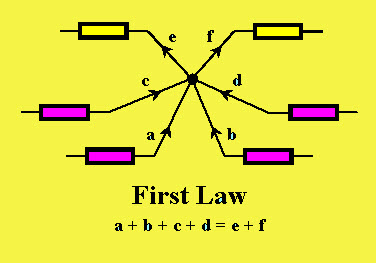
In the above diagram, the currents are denoted with a,b,c,d and e. According to the KCL law, the entering currents are a,b,c,d and the leaving currents are e and f with negative value. The equation can be written as
                                       a+b+c+d= e + f
Generally in an electrical circuit, the term node refers to a junction or connection of multiple components or elements or current carrying lanes like components and cables. In a closed circuit, the current flow any in or out of a node lane must exist. This law is used to analyze parallel circuits.

Kirchhoff Voltage Law

KVL or Kirchhoff’s voltage law or Kirchhoffs second law states that, the algebraic sum of the voltage in a closed circuit is equal to zero or the algebraic sum of the voltage at node is equal to zero.
Kirchhoff's Voltage Law
Kirchhoff’s Voltage Law
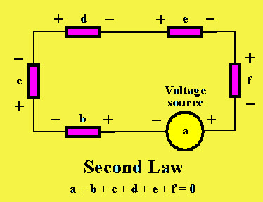
This law deals with voltage. For instance, the above circuit is explained. A voltage source ‘a’ is connected with five passive components, namely b, c, d, e, f having voltage differences across them. Arithmetically, the voltage difference between these components add together because these components are connected in series. According to the KVL law, the voltage across the passive components in a circuit is always equal & opposite to the voltage source. Hence, the sum of the voltage differences across all the elements in a circuit is always zero.
                               a+b+c+d+e+f=0

Common DC Circuit Theory Terms

The common DC circuit consists of various theory terms are
Circuit: A DC circuit is a closed loop conducting lane in which an electrical current flows
Path: A single lane is used to connect the sources or elements
Node: A node is a connection in a circuit where multiple elements are connected together, and it is denoted with a dot.
Branch: a branch is a single or collection of elements which are connected between two nodes like resistors or a source
Loop: A loop in a circuit is a closed path, where no circuit element or node is met more than once.
Mesh: A mesh doesn’t contain any closed path, but it is a single open loop, and it does not contain any components inside a mesh.

Example of Kirchhoff’s Laws

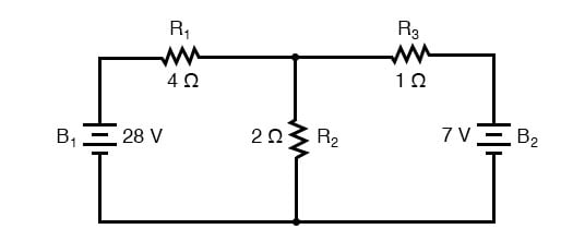
By using this circuit, we can calculate the flowing current in the resistor 40Ω
Example Circuit for KVL and KCL
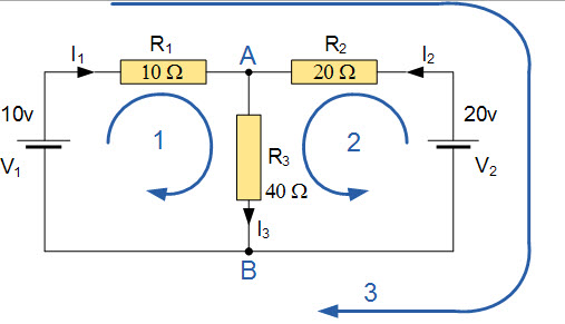
The above circuit consist of two nodes, namely A and B, three branches and two independent loops.
Apply KCL to the above circuit, then we can get the following equations.
At nodes A and B we can get the equations
I1+I2=I2 and I2 =I1+I2
Using KVL, the equations we can get the following equations
From loop1: 10=R1 X I1+R2 X I2= 10I1+40I2
From loop2: 20=R2 X I2+R2 X I3= 20I2+40I3
From loop3: 10-20=10I1-20 I2
The equation of I2 can rewrite as
Equation1= 10=10I1+40 (I1+ I2) = 50 I1+40 I2
Equation 2= 20=20I2 +40 (I1+ I2) = 40 I1+60 I2
Now we have two concurrent equations which can be reduced to give the values of I1 and I2
Replacement of I1 in terms of I2 gives the value of I1= -0.143 Amps
Replacement of I2 in terms of I1 gives the value of I2= +0.429 Amps
We know the equation of I3 = I1 + I2
The flow of current in resistor R3 is written as -0.143 + 0.429 = 0.286 Amps
The voltage across the resistor R3 is written as: 0.286 x 40 = 11.44 volts
The –ve sign for ‘I’ is the direction of the flow of current initially preferred was wrong, In fact, the 20 volt battery is charging the 10 volt battery.
This is all about Kirchoff’s laws, which includes KVL and KCL. These laws are used to calculate the current and voltage in a linear circuit, and we can also use loop analysis to calculate the current in each loop. Furthermore, any queries regarding these laws, please give your valuable suggestions by commenting in the comment section below.

SUPERPOSITION THEOREM


Superposition Theorem


Superposition theorem is one of those strokes of genius that takes a complex subject and simplifies it in a way that makes perfect sense. A theorem like Millman’s certainly works well, but it is not quite obvious why it works so well. Superposition, on the other hand, is obvious.

Series/Parallel Analysis

The strategy used in the Superposition Theorem is to eliminate all but one source of power within a network at a time, using series/parallel analysis to determine voltage drops (and/or currents) within the modified network for each power source separately. Then, once voltage drops and/or currents have been determined for each power source working separately, the values are all “superimposed” on top of each other (added algebraically) to find the actual voltage drops/currents with all sources active. Let’s look at our example circuit again and apply Superposition Theorem to it:
series parallel analysis circuit

Since we have two sources of power in this circuit, we will have to calculate two sets of values for voltage drops and/or currents, one for the circuit with only the 28-volt battery in effect. . .
series parallel analysis circuit

. . . and one for the circuit with only the 7-volt battery in effect:
series parallel analysis circuit

When re-drawing the circuit for series/parallel analysis with one source, all other voltage sources are replaced by wires (shorts), and all current sources with open circuits (breaks). Since we only have voltage sources (batteries) in our example circuit, we will replace every inactive source during analysis with a wire.
Analyzing the circuit with only the 28-volt battery, we obtain the following values for voltage and current:
values for voltage and current
series parallel analysis circuit

Analyzing the circuit with only the 7-volt battery, we obtain another set of values for voltage and current:
values for voltage and current image
series parallel analysis circuit

By Superimposing

When superimposing these values of voltage and current, we have to be very careful to consider polarity (of the voltage drop) and direction (of the current flow), as the values have to be added algebraically.
superimposing voltage and current

Applying these superimposed voltage figures to the circuit, the end result looks something like this:
series parallel analysis circuit

Currents add up algebraically as well and can either be superimposed as done with the resistor voltage drops or simply calculated from the final voltage drops and respective resistances (I=E/R). Either way, the answers will be the same. Here I will show the superposition method applied to current:
superposition method applied to current

Once again applying these superimposed figures to our circuit:
series parallel analysis circuit

Prerequisites for the Superposition Theorem

Quite simple and elegant, don’t you think? It must be noted, though, that the Superposition Theorem works only for circuits that are reducible to series/parallel combinations for each of the power sources at a time (thus, this theorem is useless for analyzing an unbalanced bridge circuit), and it only works where the underlying equations are linear (no mathematical powers or roots). The requisite of linearity means that Superposition Theorem is only applicable for determining voltage and current, not power!!! Power dissipations, being nonlinear functions, do not algebraically add to an accurate total when only one source is considered at a time. The need for linearity also means this Theorem cannot be applied in circuits where the resistance of a component changes with voltage or current. Hence, networks containing components like lamps (incandescent or gas-discharge) or varistors could not be analyzed.
Another prerequisite for Superposition Theorem is that all components must be “bilateral,” meaning that they behave the same with electrons flowing in either direction through them. Resistors have no polarity-specific behavior, and so the circuits we’ve been studying so far all meet this criterion.
The Superposition Theorem finds use in the study of alternating current (AC) circuits, and semiconductor (amplifier) circuits, where sometimes AC is often mixed (superimposed) with DC. Because AC voltage and current equations (Ohm’s Law) are linear just like DC, we can use Superposition to analyze the circuit with just the DC power source, then just the AC power source, combining the results to tell what will happen with both AC and DC sources in effect. For now, though, Superposition will suffice as a break from having to do simultaneous equations to analyze a circuit.

REVIEW:
  • • The Superposition Theorem states that a circuit can be analyzed with only one source of power at a time, the corresponding component voltages and currents algebraically added to find out what they’ll do with all power sources in effect.
  • • To negate all but one power source for analysis, replace any source of voltage (batteries) with a wire; replace any current source with an open (break).

THEVENIN'S THEOREM

Thevenin’s Theorem


Thevenin’s Theorem states that it is possible to simplify any linear circuit, no matter how complex, to an equivalent circuit with just a single voltage source and series resistance connected to a load. The qualification of “linear” is identical to that found in the Superposition Theorem, where all the underlying equations must be linear (no exponents or roots). If we’re dealing with passive components (such as resistors, and later, inductors and capacitors), this is true. However, there are some components (especially certain gas-discharge and semiconductor components) which are nonlinear: that is, their opposition to current changes with voltage and/or current. As such, we would call circuits containing these types of components, nonlinear circuits.

Thevenin’s Theorem in Power Systems

Thevenin’s Theorem is especially useful in analyzing power systems and other circuits where one particular resistor in the circuit (called the “load” resistor) is subject to change, and re-calculation of the circuit is necessary with each trial value of load resistance, to determine the voltage across it and current through it. Let’s take another look at our example circuit:

thevenin theorem power systems


Let’s suppose that we decide to designate R2 as the “load” resistor in this circuit. We already have four methods of analysis at our disposal (Branch Current, Mesh Current, Millman’s Theorem, and Superposition Theorem) to use in determining the voltage across R2 and current through R2, but each of these methods are time-consuming. Imagine repeating any of these methods over and over again to find what would happen if the load resistance changed (changing load resistance is very common in power systems, as multiple loads get switched on and off as needed. the total resistance of their parallel connections changing depending on how many are connected at a time). This could potentially involve a lot of work!

Thevenin Equivalent Circuit

Thevenin’s Theorem makes this easy by temporarily removing the load resistance from the original circuit and reducing what’s left to an equivalent circuit composed of a single voltage source and series resistance. The load resistance can then be re-connected to this “Thevenin equivalent circuit” and calculations carried out as if the whole network were nothing but a simple series circuit:

thevenin equivalent circuit diagram


. . . after Thevenin conversion . . .

thevenin equivalent circuit diagram

The “Thevenin Equivalent Circuit” is the electrical equivalent of B1, R1, R3, and B2 as seen from the two points where our load resistor (R2) connects.
The Thevenin equivalent circuit, if correctly derived, will behave exactly the same as the original circuit formed by B1, R1, R3, and B2. In other words, the load resistor (R2) voltage and current should be exactly the same for the same value of load resistance in the two circuits. The load resistor R2 cannot “tell the difference” between the original network of B1, R1, R3, and B2, and the Thevenin equivalent circuit of EThevenin, and RThevenin, provided that the values for EThevenin and RThevenin have been calculated correctly.
The advantage in performing the “Thevenin conversion” to the simpler circuit, of course, is that it makes load voltage and load current so much easier to solve than in the original network. Calculating the equivalent Thevenin source voltage and series resistance is actually quite easy. First, the chosen load resistor is removed from the original circuit, replaced with a break (open circuit):

thenin equivalent circuit diagram

Determine Thevenin Voltage

Next, the voltage between the two points where the load resistor used to be attached is determined. Use whatever analysis methods are at your disposal to do this. In this case, the original circuit with the load resistor removed is nothing more than a simple series circuit with opposing batteries, and so we can determine the voltage across the open load terminals by applying the rules of series circuits, Ohm’s Law, and Kirchhoff’s Voltage Law:

determine thevenin voltage


determine thevenin voltage diagram


The voltage between the two load connection points can be figured from one of the battery’s voltages and one of the resistor’s voltage drops and comes out to 11.2 volts. This is our “Thevenin voltage” (EThevenin) in the equivalent circuit:

thevenin resistance equivalent circuit

Determine Thevenin Series Resistance

To find the Thevenin series resistance for our equivalent circuit, we need to take the original circuit (with the load resistor still removed), remove the power sources (in the same style as we did with the Superposition Theorem: voltage sources replaced with wires and current sources replaced with breaks), and figure the resistance from one load terminal to the other:

determine thevenin series resistance


With the removal of the two batteries, the total resistance measured at this location is equal to R1 and R3 in parallel: 0.8 Ω. This is our “Thevenin resistance” (RThevenin) for the equivalent circuit:

thevenin resistance equivalent circuit diagram

Determine The Voltage Across The Load Resistor

With the load resistor (2 Ω) attached between the connection points, we can determine the voltage across it and current through it as though the whole network were nothing more than a simple series circuit:

determine voltage across load resistor

Notice that the voltage and current figures for R2 (8 volts, 4 amps) are identical to those found using other methods of analysis. Also notice that the voltage and current figures for the Thevenin series resistance and the Thevenin source (total) do not apply to any component in the original, complex circuit. Thevenin’s Theorem is only useful for determining what happens to a single resistor in a network: the load.
The advantage, of course, is that you can quickly determine what would happen to that single resistor if it were of a value other than 2 Ω without having to go through a lot of analysis again. Just plug in that other value for the load resistor into the Thevenin equivalent circuit and a little bit of series circuit calculation will give you the result.

REVIEW:
  • • Thevenin’s Theorem is a way to reduce a network to an equivalent circuit composed of a single voltage source, series resistance, and series load.
  • • Steps to follow for Thevenin’s Theorem:
    • Find the Thevenin source voltage by removing the load resistor from the original circuit and calculating the voltage across the open connection points where the load resistor used to be.
    • Find the Thevenin resistance by removing all power sources in the original circuit (voltage sources shorted and current sources open) and calculating total resistance between the open connection points.
    • Draw the Thevenin equivalent circuit, with the Thevenin voltage source in series with the Thevenin resistance. The load resistor re-attaches between the two open points of the equivalent circuit.
    • Analyze voltage and current for the load resistor following the rules for series circuits.

NORTON'S THEOREM

What is Norton’s Theorem?

Norton’s Theorem states that it is possible to simplify any linear circuit, no matter how complex, to an equivalent circuit with just a single current source and parallel resistance connected to a load. Just as with Thevenin’s Theorem, the qualification of “linear” is identical to that found in the Superposition Theorem: all underlying equations must be linear (no exponents or roots).

Simplifying Linear Circuits

Contrasting our original example circuit against the Norton equivalent: it looks something like this:

simplifying linear circuits


. . . after Norton conversion . . .

norton equivalent circuit diagram


Remember that a current source is a component whose job is to provide a constant amount of current, outputting as much or as little voltage necessary to maintain that constant current.

Thevenin’s Theorem vs. Norton’s Theorem

As with Thevenin’s Theorem, everything in the original circuit except the load resistance has been reduced to an equivalent circuit that is simpler to analyze. Also similar to Thevenin’s Theorem are the steps used in Norton’s Theorem to calculate the Norton source current (INorton) and Norton resistance (RNorton).

Identify The Load Resistance

As before, the first step is to identify the load resistance and remove it from the original circuit:

identify the load resistance

Find The Norton Current

Then, to find the Norton current (for the current source in the Norton equivalent circuit), place a direct wire (short) connection between the load points and determine the resultant current. Note that this step is exactly opposite the respective step in Thevenin’s Theorem, where we replaced the load resistor with a break (open circuit):

find the norton current


With zero voltage dropped between the load resistor connection points, the current through R1 is strictly a function of B1‘s voltage and R1‘s resistance: 7 amps (I=E/R). Likewise, the current through R3 is now strictly a function of B2‘s voltage and R3‘s resistance: 7 amps (I=E/R). The total current through the short between the load connection points is the sum of these two currents: 7 amps + 7 amps = 14 amps. This figure of 14 amps becomes the Norton source current (INorton) in our equivalent circuit:

norton equivalent circuit diagram

Find Norton Resistance

Remember, the arrow notation for current source points in the direction of conventional current flowTo calculate the Norton resistance (RNorton), we do the exact same thing as we did for calculating Thevenin resistance (RThevenin): take the original circuit (with the load resistor still removed), remove the power sources (in the same style as we did with the Superposition Theorem: voltage sources replaced with wires and current sources replaced with breaks), and figure total resistance from one load connection point to the other:

find the norton resistance


Now our Norton equivalent circuit looks like this:

norton equivalent circuit diagram

Determine The Voltage Across The Load Resistor

If we re-connect our original load resistance of 2 Ω, we can analyze the Norton circuit as a simple parallel arrangement:

voltage across the load resistor


As with the Thevenin equivalent circuit, the only useful information from this analysis is the voltage and current values for R2; the rest of the information is irrelevant to the original circuit. However, the same advantages seen with Thevenin’s Theorem apply to Norton’s as well: if we wish to analyze load resistor voltage and current over several different values of load resistance, we can use the Norton equivalent circuit, again and again, applying nothing more complex than simple parallel circuit analysis to determine what’s happening with each trial load.

REVIEW:
  • • Norton’s Theorem is a way to reduce a network to an equivalent circuit composed of a single current source, parallel resistance, and parallel load.
  • • Steps to follow for Norton’s Theorem:
    • • Find the Norton source current by removing the load resistor from the original circuit and calculating the current through a short (wire) jumping across the open connection points where the load resistor used to be.
    • • Find the Norton resistance by removing all power sources in the original circuit (voltage sources shorted and current sources open) and calculating total resistance between the open connection points.
    • • Draw the Norton equivalent circuit, with the Norton current source in parallel with the Norton resistance. The load resistor re-attaches between the two open points of the equivalent circuit.
    • • Analyze voltage and current for the load resistor following the rules for parallel circuits.

Friday 18 January 2019

How to Earn Money Online?- Tecskool

 How To Earn Money Online? 

Online Earning means making money via internet. Yes, it is possible to make money through the internet. One can get money only by an advertisement. Everyone can earn money online  but it just need a platform. For this purpose one must have one of following things:
 Own a website OR Your own blog.
 Own a Youtube channel or Join affiliate programs.
 Own Facebook group or page.
 Do freelancing.

 With the advancement of Internet -that has been taking over a huge portion of our lives, many people are searching the ways to make money online in order to increase their financial needs. In order to work online one should be very careful about the platform that has been chosen for online working. Some of the platforms could end up being scams.  Moreover one should not expect to earn on large scale when chosen online earning platform.  Few of the authentic online earning platforms, websites and resources are given below.

1. Freelancing:

One of the popular ways of online earning is freelancing and such search engines have plenty of options for online earnings. People having various skills have options for various tasks by these websites. Only the thing to do is
 Create an account
 Follow the instructions
 Then apply for the task that suits you the best
Many websites offers you to create a personal profile of your skills so that the interested client can contact and offer you directly.

2. Start your own website:

Internet has ample information that could be helpful in creating your own websites. This include  Choosing the domain.
 Choosing the template.
 Designing of your website.

 Website can be developed on www.wordpress.com or you can sign in on www.blogger.com where you can create your own blog very easily.Once all such needs are ready to serve visitors. Then signup for Google Adsense. Then ads will appear on your website and is clicked by visitors, which will assist you to earn money.
“THE MORE THE TRAFFIC ON WEBSITE, THE MORE WILL BE YOUR EARNING”

3. Affiliate marketing:

 Once the website is running and has up clicks there is an option of inserting various web links on to your website and when the visitors purchase any product from that service  you can earn from it. You can review and sell products of different e-commerce sites like www.amazon.com and www.flipkart.com and earn a good commision on the product which is purchased by your affiliate link. You can join amazon's affiliate program to earn money.

4. Surveys and searches and reviews:

There are many websites that offer
 Online surveys
 Carry out the online searches
 Write the reviews on various products.
You should use this route with supreme care. You should disclose certain information like banking details in it. Some of the websites offer you to register with them before working on various kinds of projects. Stay away from the websites that offer money and "Seems too good to be True".

5. Online tutoring:

            If you are specialist of a particular subject, you can be an online tutor.  Online tutoring will provide you the platform to connect with the students of all ages worldwide to assist them in their homework and demonstrating the subject that you will be hired for.
Few of the online websites for tutoring are:
 www.vedantu.com
 www.bharatTutors.com
 www.tutorindia.net

The only thing you will do is creating your account and then fill the instructions and start earning. Few of the websites are flexible and can allow you the convenient time to work as an online tutor.

6. Social media:

                 In order to work with your friends and as well as with strangers the various kinds of social networks can be used to make money. The popular social networks are
 Facebook
 Twitter
 Instagram
 Snap chat
   The popular brands and Companies pay social media plotters to boost the popularity of their products. Because of competition around and the constantly limitation of attention time of online viewers, the creativity is necessary to create posts, videos etc which can go viral rapidly and increases the brand value. Do remember one thing that social media needs dedicated time and of course energy to stay significant. 

Thank you for reading our article till here. Please do share your own money making ideas in the comments section. You can read our another article on
How to earn money with or without cash?